

If the volume at the ear phone plug of your smartphone/tablet is sufficient, the easiest layout of a cable for use with DSLR Remote to remotely control your camera is shown below:
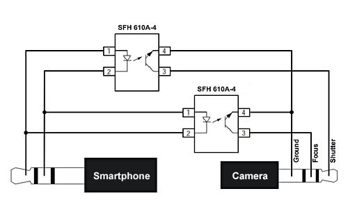 |
Mainly it consists of two opto-couplers, connected on one side with opposing polarities to the tip and center ring of a 3.5 mm stereo headphone jack and on the other side to a cable matching the built-in remote control socket on your camera. In the above layout and in the following how-to two opto-couplers of type SFH 610A-4 are used. Other types are also suitable but be aware of a possibly different pinout! The numbering in the how-to refers to the SFH 610A-4.
What you need:
- 2 opto-couplers SFH 610A-4 or the like
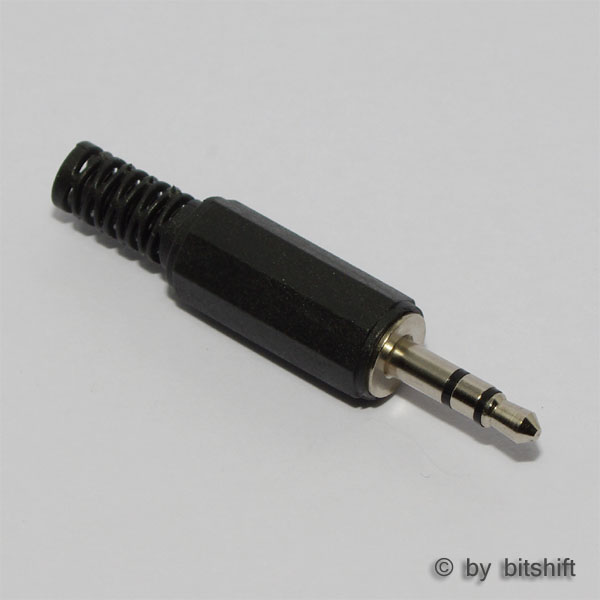
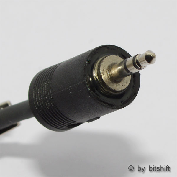
- 1 stereo audio jack, 3.5 mm
- 1 cable with jack matching the remote control socket on your camera (here: stereo audio jack, 2.5 mm)
- instant glue
- duct tape or better heat-shrink tubing
- side cutter or equivalent
- soldering iron and solder tin
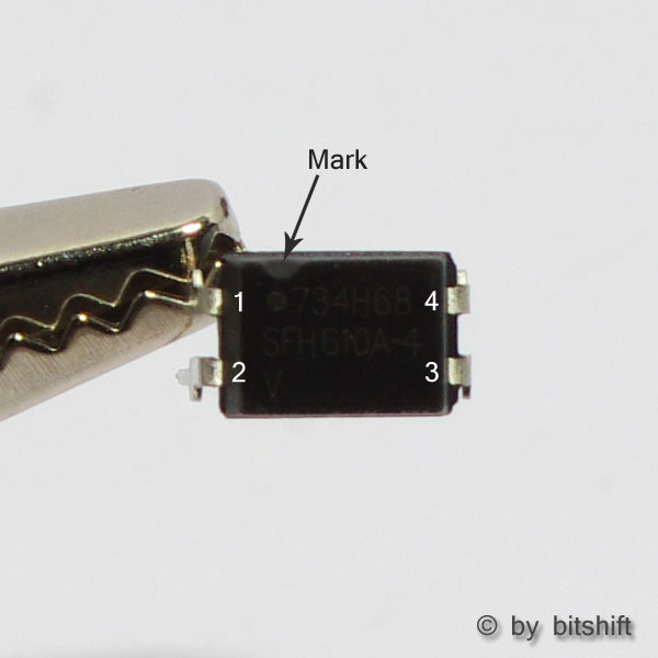
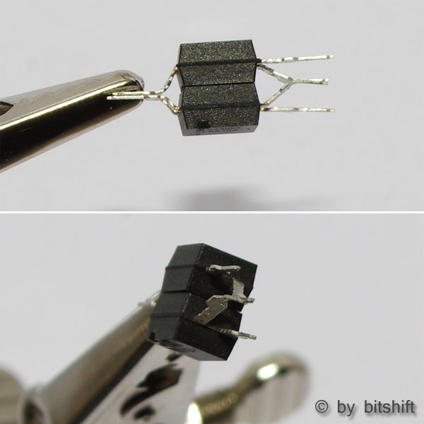
In the picture to the left a SFH 610A-4 is shown from above. A groove or a dot marks the pin with the number 1. From here counting proceeds counter clockwise.

Straighten the leads of the opto-couplers...
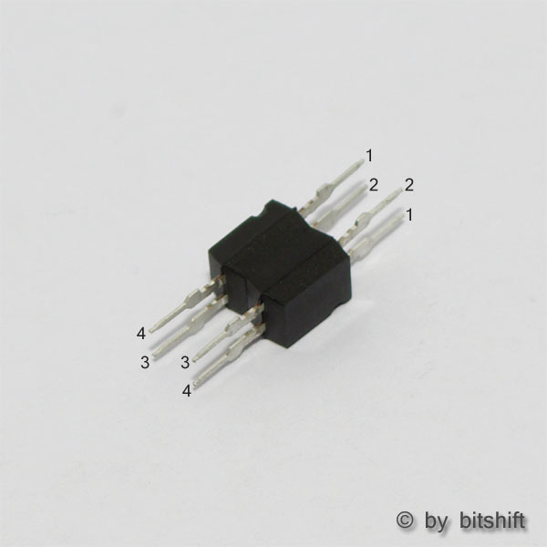
...and glue them together bottom to bottom with some instant glue in a way that the printing on top is still visible. On one side the pins 1 and 2 from one opto-coupler must face the pins 2 and 1 respectivelly of the other opto-coupler. On the other side the pins 3 and 4 must face the opposing pins 4 and 3.
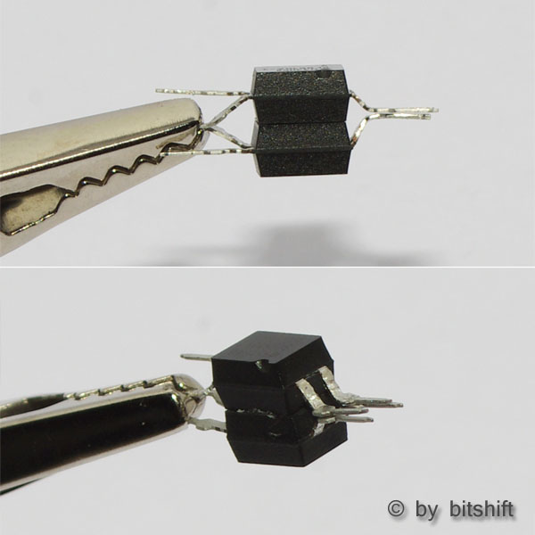
Bend the lead pairs of pins 1 and 2 together.
Maybe you have to shorten the leads from pins 1 and 2 to avoid short-circuiting the connectors in the 3.5 audio jack.
Unscrew the cover of the audio jack...
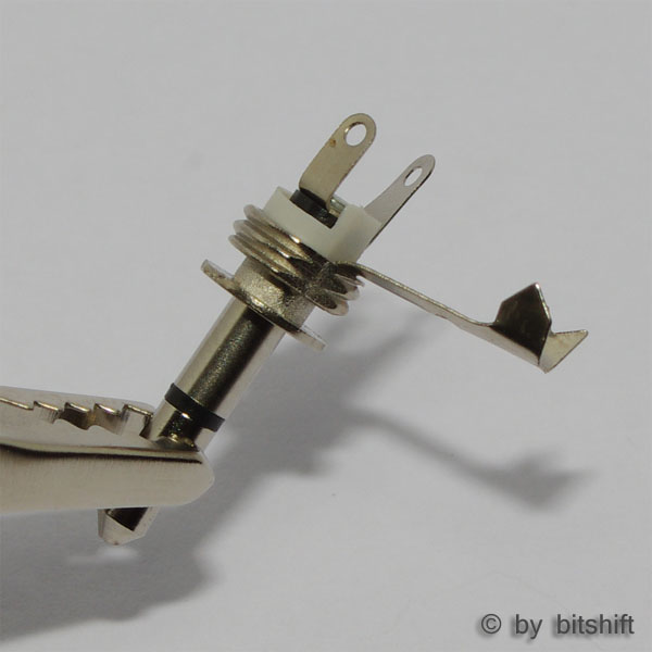
...and remove the ground connector...

...by bending it forth and back several times.
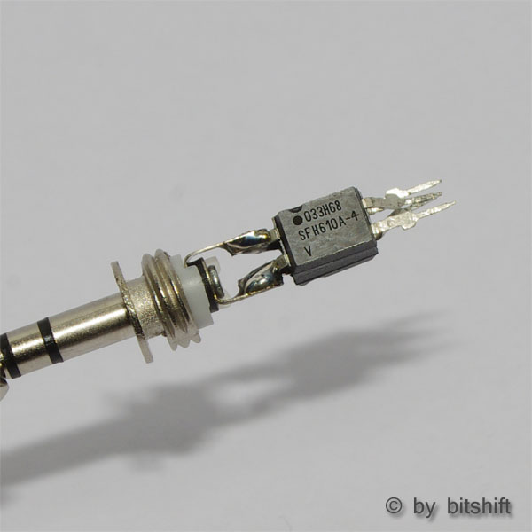
Solder the opto-couplers to the two remaining connectors of the audion jack in a way that one pin 1 and 2 pair each is soldered to one connector. Use an extend of solder tin to increase mechanical stability as the final cable has no cable relief.
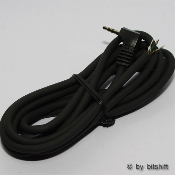
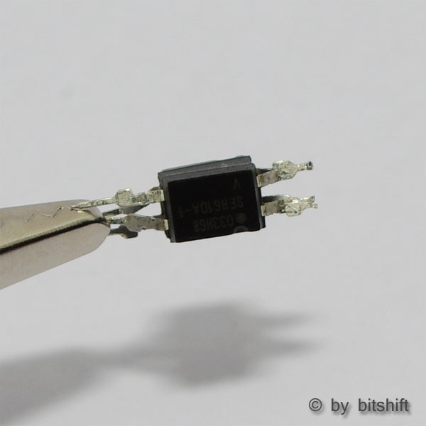
In the picture to the left a ready-made cable with a 2.5mm audio jack on one side is shown. Many types of cameras use such a jack for connecting a shutter release cable to the camera. If your camera needs a different connector or a different pinout please use an appropriate cable instead.
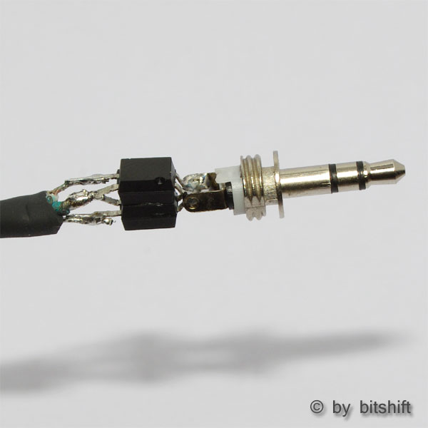
Now solder the ground wire of the cable to the two pins 4. The shutter wire (tip of the 2.5 mm audio jack) has to be connected to pin 3 of the opto-coupler whose pin 1 is connected to the tip of the 3.5 mm audio jack. The focus wire (center ring of the 2.5 mm audio jack) has to be connected to pin 3 of the opto-coupler whose pin 1 is connected to the center ring of the 3.5 mm audio jack. If this sounds somewhat confusing, there's a 50-50-chance for you to connect the two wires in the correct orientation. So next thing to do is to check the proper function: start DSLR Remote and plug the 3.5 mm jack to the audio connector of your smartphone/tablet. Plug the 2.5 mm jack to the matching connector of your camera and switch on the camera. If not already done choose the remote type Cable in the settings of DSLR Remote and move to the remote frame. You should find two buttons here: S for Shutter and F for Focus. If you press the button F now your camera should focus. If it does you did connect the wires in the correct way. Now check the shutter function by pressing the button S to make shure this works as well.
If your camera takes a shot when F is pressed and just focus respectivelly if S is pressed you switched the wires und have to solder them the other way around.
To achieve a higher mechanical stability you should cover the whole with glue or hot glue. By doing so you get some sort of cable relief, to protect the soldering joints from beeing torn off by drag on the cable during usage. Finally for a better look you can cover the whole with duct tape or heat-shrink tubing.
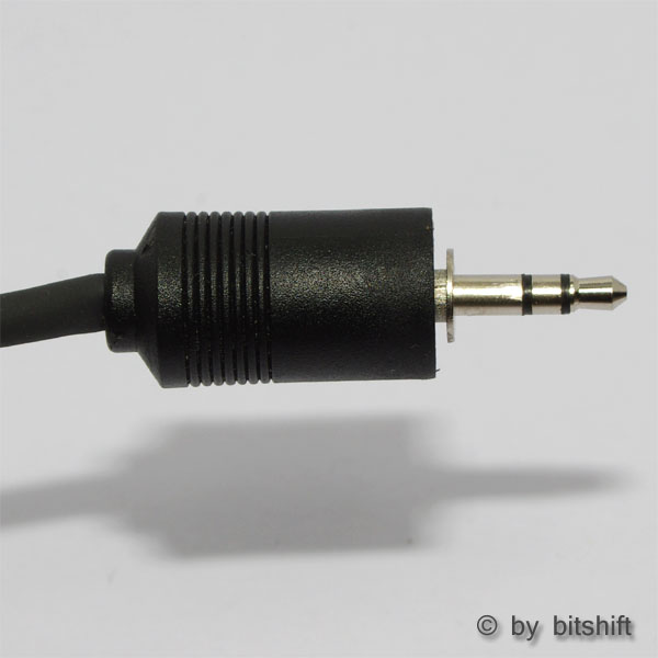
Here the cover of an abundant bigger audio jack was placed over the opto-couplers and the upper part of the 3.5 mm audio jack. Finally it was filled with epoxy resin.
Ready to use! |
|
 |
 |
For those with soldering experience and a steady hand
A cable with two opto-couplers of type LTV 352T (SMD) finding enough space in the original cover. Caution: the pinout on the transistor side of the LTV 352T is swapped as compared to the SFH 610A-4! The pins 3 have to be connected together to the ground wire and the two pins 4 to a signal wire each.
 |